The tutorial will be broken up into three sections. The first section will be a basic illustration of using the asterize control dialog. The second portion will deal with manipulating the Arm Profile graph. The final section will show you how to create an actual animation with the asterize operation.
- 1 - This section of the tutorial will introduce you to the Edit Profile control which gives the asterize operation all of its power. Let's begin this section with another new image (follow the steps in the previous section on creating a new image.) Once the new image is created, select the Four Star preset, and apply an asterism to the new image. This should look something like this:

Now, press the button which says Edit Profile. The Edit Profile control allows you to alter the arm profile of the asterize operation. The arm profile is the color and width of each arm in the asterization. The graph is read from left to right (Clockwise along the arm). The vertical axis of the graph is the brightness or color of each portion of the arm, and the horizontal axis determines the length of each portion of the arm. You will notice that as the graph increases vertically that the color of the arm is getting closer to the peak color, and that as the graph decreases vertically that the color of the arm is approaching the edge color. It is important to remember that the arm profile that is specified will be used for all of the arms in the asterism. The profile is altered by simply drawing the desired profile using the left mouse button. There are several tools to aid in the creation of new profiles. The arm profile graph for the Four Star Preset will look like this:
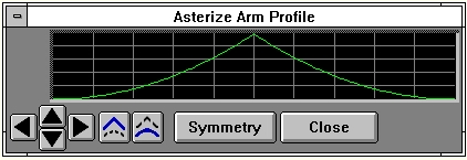
So using the above information, this graph tells us that each arm should reach the peak color near the middle of the arm, and then taper off in either direction towards the edge color, which is exactly what happens.
- Now, let's actually alter the arm profile to create a new asterization. The graph itself is altered by simply drawing on the graph while holding down the left mouse button. You will want to bring the center of the graph (which is at the peak color) to the bottom of the graph. Next, pull down the graph that is to the left of the center up to the first vertical division mark. Now, press the button marked Symmetry. This will cause the left and the right sides of the graph to have a reflective symmetry based on the graph information on the left. This tool is very useful in creating very symmetric arms. After you have completed this, the graph should look like this:
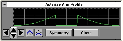
If you were to apply this graph with the current settings, you would get a very dark asterization that would be hard to see. This is due to the fact that the edge color (bottom of the graph) is very close to the image color of black. One way to make the asterism more visible is to move the entire graph up, so that the colors used will be nearer the peak color. To accomplish this, simply press the up arrow icon on the left-hand side of the profile graph until the two peaks just touch the top of the graph.
This new graph will create an arm that has two arms that reach the peak color and fade back to the
edge color. Let's apply this new profile, and see its effects. You may now close the trend graph by
pressing the Close button. Now, select an ellipse above and to the left of the original Four Star
Asterism. The final result should look like this:

When this operator is dragged into the timeline,
profiles will automatically trend to the next profile, if another exists in the timeline.
- You have now applied a new arm profile using the arm profile graph. You have the option of using the default profiles, or creating your own. It is important to remember that once you have altered the profile you should not press any of the preset buttons. WinImages F/x also allows you to save any arm profile that you create. This is done by pressing the Save button at the bottom of the asterize control dialog. These settings can then be loaded and used at any time by pressing the Load button. You should take the time to manipulate the arm profile graph, and then view its effects. Once you feel comfortable using the graph, move on to the next section of this tutorial.
- This section of the tutorial is designed to give you a step by step example of producing an animation using the Asterize operation. This tutorial will rely on your knowledge of the information provided in the previous two sections. If you have not read and completed Part 1 and 2 of the Asterize tutorial, do so before beginning this section. Let's start with a fresh image for this example. Follow the instructions for creating a new image in Part 1 of this tutorial section. The image should follow the specification made there (320 x 200 and black). After this is complete, make sure that the asterize dialog is visible by selecting the Asterize icon in the Lighting group, or by selecting the Asterize option in the Operations pull down menu.
- The next step in the animation process is to set all of the output parameters in the Sequence Controls dialog. You can access this dialog by selecting the Time Line pull down menu, and then the Sequence controls... option. This will open a dialog which allows you to set the number of frames, output file type, and the name and path of the animation to be saved. The first thing to set in this panel is the Total Frames option. This option allows you to specify the total number of frames in the animation. This can range anywhere from 3 to more than 64,000 frames! The demonstration animation (located near the end of this tutorial) was created using 45 frames. For this example, set the Total Frames to a value between 15 and 30. If you find the animation is not smooth enough, increase the number of frames.
The next step is to select the output format. The format can be any of the available file types including AVI and FLI/FLC animations. The file type is selected by clicking on the down arrow to the left of the Output Format drop down box. Clicking this will access a scrolling list requester which can be used to set the output format. We may want to use this animation in a later tutorial so select either AVI or FLI/FLC for simplicity. Next, you will want to set the Output Image Path and File Name You can select any valid directory and image name, or use the Specify button to access a file requester for directory and name specification. It is important to remember to select a valid directory and name, or the animation could be saved in the wrong location, or the file name may be truncated. You should also set the extension if it is different from the default setting. For example, if you are creating an AVI, set the extension to AVI. There is no need to add the "." in front of the extension because WinImages F/x does this for you. The final option to set is the Save Results check box. If this check box is selected, the animation will be saved in the specified format to the selected directory. If you do not wish to save this or any other animation sequence, do not select this option. When the save option is not selected the animation will only be created for viewing in the filmstrip. This allows you to rapidly preview an effect or group of effects. Once you have decided on saving or not saving the animation, press the Ok button to exit this dialog.
- The animation that we are going to create will be a four armed asterism that changes colors and rotates in the center of the image. This will require that you set some of the available Trend Graphs. The Trend Graphs are used to specify a particular parameter over time. For example, if we wanted to have an asterism rotate from 0 to 360 degrees over the course of the animation, we would have to set the trend graph for the Rotate option in the Asterize dialog. If you have further questions on trends or the trend controls, please review the section in the main Asterize documentation. This animation will use the arm profile provided by pressing the Four Star preset button. If you have not already done so, press the Four Star preset.
- Now that we know what type of operation we are going to create, we will need to open the Time Line. The Time Line is a powerful key frame based animation controller. It allows you to specify which operations, area selections, and image files will be used to create an animated sequence. The time line dialog can be accessed by selecting the time line icon from the tool bar, or by selecting the Show TimeLine option from the TimeLine menu. The time line should appear with the current operation in the first frame. We will want to start with a fresh time line, so select the Erase Time Line button to clear the current time line dialog. Now, select the asterize icon from the tool bar, and place it into frame one of the time line. This method is known as Drag and Drop, and it is used to place operation and area selection key frames into the time line. The Asterize operation will have been placed with all of the current settings information.
In order to create the desired animation, we will need to set a trend graph for the rotation and green parameters. This can be done by double clicking on the asterize operation icon in frame one of the time line. This will access the Time Line Operation dialog. This dialog contains controls for obtaining current settings and trends from dialogs, or for setting new values for an operation parameter or trend. For this example, you will want to select the Set Trends option. This will bring up a dialog which contains a list of all of the available trends for the asterize operation. You will want to select the Arm Green trend, and then press the Adjust this trend button. This will open this trend for manipulation. Also open the Saturation and Rotation trends using the same method. Once you have opened these two trends, select the Ok button to close the dialog.
- We now have two trends available for adjustment. The first trend that we will adjust is the rotation trend. The initial rotation trend graph should look like this:
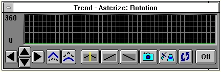
As you can see the trend for this control is set to 0 degrees rotation for each frame. We would like to have an animation that ranges from 0 to 360 degrees over the entire length of the animation. To do this we simply click on the button with the line that goes from the bottom right (minimum) to the top left (maximum). After you have done this, the graph will look like this:
This is exactly the effect that we are looking for. The asterization will begin on frame one with 0 degrees rotation, and will finish near 360 degrees on the final frame. WinImages F/x will automatically reduce the final value of any trend that ranges from 0 to 360 degrees. This is to eliminate "bumps" in a looping animation. You can manually move the final frame value up to 360 degrees. If you do this, you will notice that the animation will have two frames which are exactly the same (0 and 360). You can also manually specify each frame value by "drawing" on the graph with the left mouse button down. This allows you to visually set each frame, or a single frame to any value you like. You can exit the trend by pressing the Ok button.
Now that you have set the Rotation trend, set the Green and Saturation trends to the exact same settings. This will produce an asterism that not only rotates, but also changes colors from dark blue to purple, and will have an increasing saturation value. This is done by simply pressing the button with the line going from the bottom left to the top right for both the Green and Saturation trends. After you have done this for both trends, select the Ok button to close the trend graphs.
- We have now finished setting all of the parameters for the asterization. We will now need to set an area select for the operation to occur in. For this example, you will need to select the Ellipse area selection tool from the tool box. This example is also going to show you how to create an effect that fades in, and then fades back out. This can all be accomplished through the time line. First, place an ellipse area selection into the first frame of the time line using the Drag and Drop method described above. Now, double click on the ellipse area selection icon in frame one. This will open the Area Selection Object dialog. This dialog contains controls for making and altering area selections. Choose the Make the area selection now option. This will bring the current action image to the front. Now, click and hold the left mouse button near the center of the all black image. You will now be able to size out an ellipse by holding the left mouse button, and moving the mouse. You may reposition the ellipse by pressing the right mouse button at the same time as the left.
|
Warning:
 |
If you release the left mouse button the operation will be executed. If this occurs, select the Undo option, and try again. |
|
The ellipse should be about one quarter the entire size of the image, and approximately centered. This area selection will automatically be placed into the time line when you release the left mouse button.
Now we will set the transparency for the animation sequence. The area selection transparency controls are located in the Area Selection Details dialog. This dialog can be accessed by double clicking on the ellipse icon in the time line, and then selecting the Show Details option. This dialog contains the controls for altering the transparency of an area selection. These controls allow you to set the transparency and blending for any operation or area select. If you would like to view further information on these controls, press here, and then look for the section headed Transparency Controls.... To achieve the desired effect, select the trend for the Level control, and then select the Ok button.
|
Note:

|
You will not be able to edit the Level trend until you select the Ok button in the Area Selection Details dialog. |
|
The Transparency Level trend should be set to a linear setting of 255. This means that the effect will be completely visible for the entire animation. For this example, we will want to have the effect change from not visible to visible, and then back to not visible. Using the left mouse button, set your trend graph to look like this:
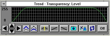
This will give us the desired fade in, and then a fade out. Once you have set the trend, select the Ok button to exit.
- We are now ready to create our animation. If your filmstrip is not currently visible, please turn it on by selecting the Show Filmstrip option in the Filmstrip pull down menu, or the filmstrip icon on the tool bar.
|
Note:
|
If this option already has a check mark by it, the filmstrip is already "on". This means that you will not have to select this option. |
|
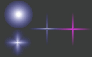
Once the filmstrip is visible, select the Generate option from the Time Line dialog. WinImages F/x will now begin to process the specified animation using the trends and area selection information that you provided. The final result should look like this:
Play Animation
You have now completed the Asterize tutorial. This tutorial can serve as a good base for other examples and tutorials. Not all of the tutorials will be as extensive as this one, but you can apply many of the same techniques to WinImages F/x's other operations. As a further example of some of the things you can do in an asterize animation, play the example below.
Play Animation
Page 309
WinImages F/x, WinImages Morph and all associated documentation
Copyright © 1992-2007 Black Belt Systems
ALL RIGHTS RESERVED Under the Pan-American Conventions
| WinImages F/x Manual Version 7, Revision 5, Level B |
HTML Documentation Management System © 1992-2007 Black Belt Systems

