|
|
 |
 |
 |
 |
 |
 |
 |
(Click any button to go to the documentation for it)
| Quick Nav Bar | ||||||||
|---|---|---|---|---|---|---|---|---|
| << Previous | Contents |
Selection |
Op Index |
Parent | User Notes |
Index |
Glossary |
Next >> |
|
|
|
|
|
|
|
|
|
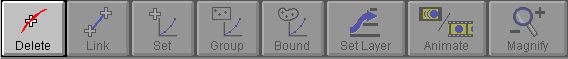
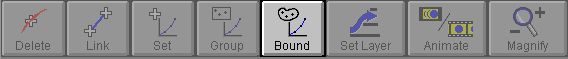
Will remove the currently selected point (and any links connected to it) or line .
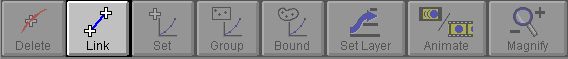
If you click on this button it will stay selected until you click on it again. With this button down clicking with the left mouse button on two points will connect them with a link. Clicking on two points that are already connected with a link will remove the link. To prevent connecting a point with the last selected point click on the selected point again and it will become de-selected. Links are not available between lines and other control objects.
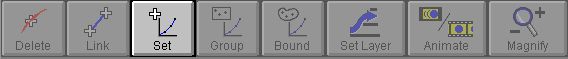
Sets the velocity or transparency curve assignment for the currently selected point or line. It is important to remember that this is the only way to specify a transparency or velocity curve for an object that is not a point. You cannot specify more than one choice of transparency or velocity information for the same obhject. For example, you can not specify the top half of a line as an early transparency curve, and the bottom half as a late transparency curve. The entire line must be a specific transparency setting. For this reason, if you're planning a project that will require variations in transparency and/or velocity, make sure that you use different objects for each region that will require a different curve or either type.
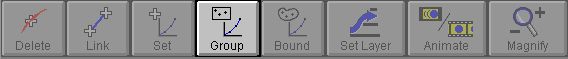
After clicking this button, the program will ask for either Velocity or Transparency to be set. Then you'll draw a rectangle on either the start or end images. The program will then present a list of velocity or transparency curves. All points that lie within the rectangle you drew will be assigned to the selected curve. All points which are assigned to this curve will be redrawn with a red outline. You cannot use this option to specify a transparency or velocity curve for a control line or curve. Velocity and transparency information can be set for lines and curves using the Set button.
After clicking this button, the program will ask for either Velocity or Transparency to be set. Then you'll draw a freehand shape on either the start or end images. The program will then present a list of velocity or transparency curves. All points that lie within the shape you drew will be assigned to the selected curve. All points which are assigned to this curve will be redrawn with a red outline. You cannot use this option to specify a transparency or velocity curve for a control line or curve. Velocity and transparency information can be set for lines and curves using the Set button.
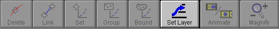
The Layer button in the tool bar allows you to specify control objects into layers of control. You may be wondering what a layer even is, and how it can benefit your morph sequence. Layers and layering allow you to separate various objects from the rest of the morph, and morph them independent of objects not in the same layer. For example, the Bounce motion morph project uses two layers. The first layer (also known as the Base Layer) contains no control objects, and is essentially the background of the motion morph frames. The second layer contains 1 object (the circle and square outlines), which is place above the background. When the morph is generated, the base layer is created first, and then any subsequent layers that have been specified. In this case there is only one other layer, so it is created and placed on top of the base layer. The overall effect is the ball morphing into the square without ever altering the background information.
Each layer that is specified can contain any number of control objects, and is morphed independent of all other layers. Each layer can contain any number of transparency and velocity information as well. It is very important to remember that each specified layer must be a closed region, or have a surrounding boundary area. For example, an eye may have several components that are within an outline of the outer eye. The outer eye object should be closed (with a link between the endpoints of the line-sequence if it is an open object like a polygon) and then the other objects inside the boundary should be added. If you specify layers that are not closed, then the morph will not be able to generate. In general, creating a layer is very simple:
|
It is important to remember that the morph can not be generated if area boundary layers are not closed. This can be checked by selecting the area boundary object by pressing the Ctrl key and then left clicking on it. After you have done this, press the Layers button to access the layers dialog. If this object has already been placed into a layer, that layer will appear highlighted. At the bottom of the display you should see a small readout that says: Area is Closed or Area is NOT Closed. If all of the boundary areas are closed, then the morph will generate without any further alteration. If the current object is a boundary (Area Boundaries will have the area boundary setting checked in the layers dialog) and it is not closed, the morph will not be able to generate. Once you have determined that an area boundary is not closed., you can proceed to close it. This is done by selecting the point tool in the object tool box, and then pressing the Links button in the Icon Bar. Links are the only method of closing unbounded shapes like curves and lines. The linker can be used to close the area boundary by selecting the desired object (Ctrl left click on the object), and then clicking on it a second time to place the link. If the ends of the line or curve are close together the two ends will be linked automatically. If the ends of the object are further apart, the edge will connect the end off the line closest to the initial click with the object closest to the final click. After you have closed the area boundary with a link, turn of the linking mode by left clicking on the link icon. Enter the Layers dialog with the area boundary selected. The readout should now state that the region is closed. If it does not review where the links were placed, and try again to close the area boundary. You will not be able to generate the morph until this boundary is closed.
Controls:
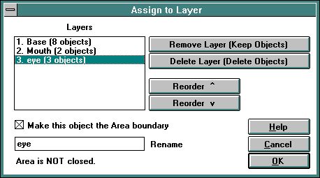
Layers
This portion of the dialog contains a list of all of the layers, and how many objects are in that layer. The example layers dialog contains three layers (Base, Mouth, and eye) each with a number of objects in the layer. You should notice that the "eye" layer is selected, and at the bottom of the dialog it states Area NOT closed. This morph sequence would be unable to generate because the layer is not closed. Layers are formed of boundary objects (must be closed) and objects inside the boundary object (do not have to be closed).
This portion of the dialog also displays the priority or depth of each of the layers. The further down the list a layer gets, the higher it gets. For example, in the morph example above the Base layer would be morphed first, then the Mouth layer, and finally the Eye layer.
OK
Clicking OK will assign the object that was selected when you entered the layer dialog to the layer that was most recently clicked in the layer dialog. So if you were moving layers around and otherwise clicking on various layers, make sure you click on the layer that should contain the currently selected object prior to pressing the OK button. Assignment occurs every time the dialog is closed with OK - remember what the buttons says: "Set Layer"
If you don't want to assign, or re-assign, a layer, use CANCEL to exit the dialog. Moved layers will remain re-ordered, but no layer assignment will take place.
Add New Layer:
This option will place a new layer in the list of possible layers for the morph. Once created, the new layer can be named and have control objects placed into it. It is very important to remember that new layers must have an area boundary, and this boundary must be closed. If these conditions are not met, the morph will not generate properly. Review the previous two paragraphs for more information on area boundaries and closing them.
Remove Layer (Keep Objects):
This option will delete the currently selected layer (and all related information), but it will leave the objects in the view windows. This allows you to eliminate layer associations without eliminating specified objects.
Delete Layer (Delete Objects):
This option will delete the currently selected layer, and all of the objects within that layer. Once this button has been pressed, all of the objects in that layer will be deleted from the image views.
Reorder ^:
This will move the currently selected layer up one position. It will move the layer that is above it into its initial position. This is true for all layers except the Base layer which can not be moved.
Reorder v:
This will move the currently selected layer down one position. It will move the layer that was below it into its initial position. This is true for all layers except the Base layer which can not be moved.
Make area boundary:
This option, when selected, will make the currently selected object into an area boundary for a layer. This means that this object must be closed, and all other objects in the layer must be found within its boundaries. If this is not the case, the morph will not generate properly. If this option is not selected, then the object will be treated like any other object in a layer.
Rename:
This option allows you to alter the name of the currently selected layer. This can be useful for defining particular regions in an image all within the same layer heading. You may alter the name of every layer except the Base layer.
Area Status:
This status line tells you whether the currently selected layer is closed or not. Remember, layers that are not closed will cause the program to halt creation of a single image or sequence. Layers (or layer boundaries) can be closed with a link.
Animate
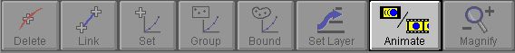
This displays the film strip if it is not already displayed and starts it animating. Clicking on the button again will stop the animation.
Zoom/Negative Zoom
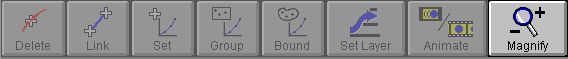
The Zoom/Negative Zoom button is broken into two sections. The top right section of the icon allows you to access the zoom tool, and the bottom left side of the icon allows you to access the negative zoom tool. After pressing the Zoom button, morph will alter the cursor to look like a magnifying glass. You can then draw a rectangle on either the Start, End, or Result images. The area inside the rectangle will be zoomed to fill the entire window. If you simply click in the view window, WinImages Morph will do a 2X zoom with the center of the zoom being where you initially clicked.
To draw a rectangle for this, or any other function:
Pressing the Negative Zoom button allows you to select a view to be de-zoomed. If you only have one view zoomed, WinImages Morph will automatically de-zoom the view. Selecting negative zoom on an unzoomed image will result in the image being zoomed out -2x. This means that the image will appear within a solid color background smaller than full size.
| Quick Nav Bar | ||||||||
|---|---|---|---|---|---|---|---|---|
| << Previous | Contents |
Selection |
Op Index |
Parent | User Notes |
Index |
Glossary |
Next >> |
| WinImages F/x Manual Version 7, Revision 5, Level B |