
| Quick Nav Bar | ||||||||
|---|---|---|---|---|---|---|---|---|
| << Previous | Contents |
Selection |
Op Index |
Parent | User Notes |
Index |
Glossary |
Next >> |
| a=WAVES(xwaves, xfront, xside, ywaves, yfront, yside, shading, xphase, yphase) |
| Items in CAPS are 0/1 switches or switches with more options than 0/1. |
|
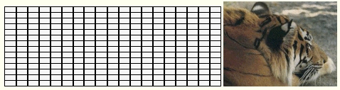
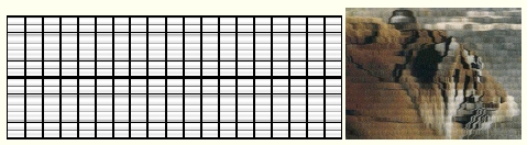
The Waves operation allows you to create horizontal and vertical waves on the image. These waves and effects are similar to the patterns found in nature, and every day objects. You can create effects like a heat wave, a fun house mirror, or a textured glass effect. You can control the number of vertical and horizontal waves, direction and type of wave, and shading. The waves will begin from the center of the area selection, therefore the center will have the greatest amount of distortion. Since some of these concepts may be difficult to understand, there are four preset effects. The detailed documentation below also contains example images based on an image of a grid so that you may see what is physically happening to the image, and an image of a tiger with the same effect applied to it. This will help you to better understand the way that the control affects the image. The initial grid image and tiger image look like this:
Due to the compute intensive nature of this operation, generation of this effect can be very slow on machines without a math coprocessor.
Trends
You will notice that all of the controls have a Trend button next to them. The trend button allows you to set that variable over a set of frames. Each frame of the animation can be thought of as a slice of time. The trends allow you to alter some, all, or none of the variables for a particular time slice. You will notice that the trend graphs have equidistantly spaced vertical lines. Each of these lines represents a frame in the animation. The number of frames can be altered using the Sequence controls... in the Timeline pull down menu. Animation lengths of 100 - 999 frames will be represented with a vertical bar being 10 frames, and animation length greater than 1000 frames will have a vertical bar for every 100 frames. Click here to view more information on Trends.
X Waves
The X Waves control allows you to specify the total number of half waves in the selected area parallel to the x-axis of the image. Waves can be made up of two half waves - a peak and a trough. The peak is the maximum positive value, and the trough is the maximum negative value. For this operation all waves can be considered to ideal sinusoidal waves. This means that the maximum positive and negative values (peak and trough) are equal, and there is an equal distance between peaks and troughs. Since a complete wave is made up of two half waves, all even values will produce a complete wave. For example, a setting of 100 would result in a total of 50 peak/trough pairs parallel to the x axis. All waves will begin from the center of the selected region. This will cause that center point to have the greatest amount of distortion. If this control is set to 1, no X Waves will be applied to the image. A minimum setting of 2 half waves is required for application.
X Front
The X Front control allows you to specify the size of the waves that move parallel to the X axis. This means that the move from the center of the area select to the area selection's top to bottom in a sinusoidal fashion. For example, the grid image below has a total of 5 X Front waves with a magnitude of 50.
The area in the center of the image (which is also the center of the area selection) contains the greatest amount of distortion. This control can range between -200 and 200, were negative values will reverse the wave. This means that the maximum amount of distortion will occur towards the edge of the area selection instead of the center. The diagram below demonstrates this point.
The value that you are specifying can also be thought of as the amplitude of the initial wave pulse. Negative values are considered negative amplitudes (trough), and positive values are considered to be a positive initial amplitude (peak).
X Side
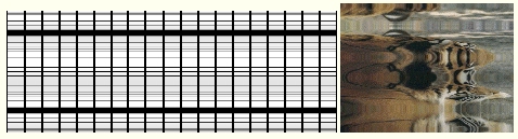
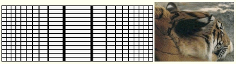
The Side wave control is used to specify the amplitude of X waves that are perpendicular to the X axis. These waves are similar to compression waves. The side waves are also sinusoidal in nature, and the amplitude of the waves will increase or decrease based on this setting. The image below shows a grid that has had a total of 5 waves applied to it. All of the waves in the image are Side waves.
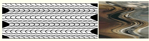
Notice that this application of only side waves, to the entire image, caused portions of the original image to be "peeled up" from the background. This explains the black regions on the left and right sides of the image. This can be avoided by specifying lower amplitude waves, or by selecting region away from the edge of the image. In some cases this peeling effect may be desired, and can be enhanced by increasing the number of waves or the amplitude (Side value). The Side value can range from -200 to positive 200, and follows the same guidelines as the Front waves described in the previous section.
Application of both Front and Side waves can produce interesting and unusual wave patterns on your image. The following image contains a total of 10 side and front waves applied at an amplitude of 50.
The overall effect is similar to the Bumpy Glass preset, but is more dramatic in effect. Since WinImages F/x allows you to apply the front and side waves for the X and Y dimensions independently, the possibilities are nearly limitless. Some experimentation on your part may result in a stunning new effect.
X Phase
The phase control allows you to shift the position of the peaks and troughs of the X waves over the course of the animation. This control ranges between 0 and 360 degrees, where 0 and 360 are the same value. For example, if you were to trend the X Phase from 0 to 360 over the animation sequence, you would see the peaks and troughs of the waves slowly change positions. This type of effect can be used to create undulating waves, or other motion based wave effects. This will only cycle the X waves, the Y waves will not be altered by this control.
Y Waves
The Y Waves control allows you to specify the total number of half waves in the selected area parallel to the y-axis of the image. Waves can be made up of two half waves, a peak and a trough. The peak is the maximum positive value, and the trough is the maximum negative value. For this operation all waves can be considered to ideal sinusoidal waves. This means that the maximum positive and negative values (peak and trough) are equal, and there is an equal distance between peaks and troughs. Since a complete wave is made up of two half waves, all even values will produce a complete wave. For example, a setting of 100 would result in a total of 50 peak/trough pairs parallel to the y-axis. All waves will begin from the center of the selected region. This will cause that center point to have the greatest amount of distortion. If this control is set to 1, no Y Waves will be applied to the image. A minimum setting of 2 half waves is required for application.
Y Front
The Y Front control allows you to specify the size of the waves that move parallel to the Y axis. This means that the move from the center of the area select to the area selection's top to bottom in a sinusoidal fashion. For example, the grid image below has a total of 5 Y Front waves with a magnitude of 50.
The area in the center of the image (which is also the center of the area selection) contains the greatest amount of distortion. This control can range between -200 and 200, were negative values will reverse the wave. This means that the maximum amount of distortion (stretching) will occur towards the edge of the area selection instead of the center. The diagram below demonstrates this point.
The value that you are specifying can also be thought of as the amplitude of the initial wave pulse. Negative values are considered negative amplitudes (trough), and positive values are considered to be a positive initial amplitude (peak).
Y Sides
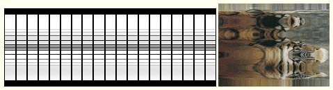
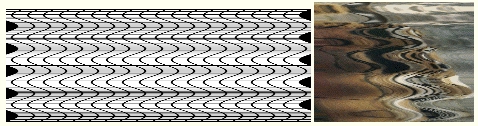
The Side wave control is used to specify the amplitude of Y waves that are perpendicular to the Y axis. These waves are similar to compression waves. The side waves are also sinusoidal in nature, and the amplitude of the waves will increase or decrease based on this setting. The image below shows a grid that has had a total of 5 waves applied to it. All of the waves in the image are Side waves.
Notice that this application of only side waves, to the entire image, caused portions of the original image to be "peeled up" from the background. This explains the black regions on the top and bottom of the image. This can be avoided by specifying lower amplitude waves, or by selecting region away from the edge of the image. In some cases this peeling effect may be desired, and can be enhanced by increasing the number of waves or the amplitude (Side value). The Side value can range from -200 to positive 200, and follows the same guidelines as the Front waves described in the previous section.
Application of both Front and Side waves can produce interesting and unusual wave patterns on your image. The following image contains a total of 10 side and front waves applied at an amplitude of 50.
The overall effect is similar to the Bumpy Glass preset, but is more dramatic in effect. Since WinImages F/x allows you to apply the front and side waves for the X and Y dimensions independently, the possibilities are nearly limitless. Some experimentation on your part may result in a stunning new effect.
Y Phase
The phase control allows you to shift the position of the peaks and troughs of the Y waves over the course of the animation. This control ranges between 0 and 360 degrees, where 0 and 360 are the same value. For example, if you were to trend the Y Phase from 0 to 360 over the animation sequence, you would see the peaks and troughs of the waves slowly change positions. This type of effect can be used to create undulating waves, or other motion based wave effects. This will only cycle the Y waves, the X waves will not be altered by this control.
Shading
The shading slide gadget allows you to specify a percentage value for the shading of the waves. This value can range from 0 (no shading) to 100 (maximum shading). The shading of the waves will help to make the differences between troughs and peaks more pronounced. The amount of shading that you use is entirely based on the type of effect that you are trying to achieve. All shading is applied to the trough of the wave.
Presets
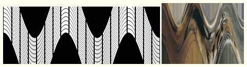
Heat Waves: The Heat Waves preset will create waves on your image that are similar to the refraction of light by convection cells on a hot summer day. This creates a wavy or "mirage" like appearance. This is due to the layers of air that are various temperatures reflecting light in different amounts. This wave is created in WinImages F/x by specifying only X waves (30 half waves - 15 total waves) with a side amplitude of 50. There is only a slight amount of shading applied to complete the effect. The overall result is very similar to the natural phenomena. The grid below shows the application of this preset to the entire image.
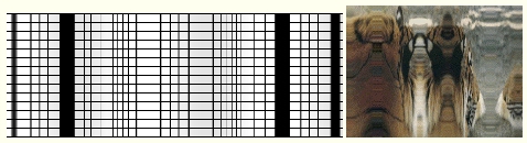
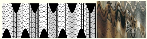
Bumpy Glass: The Bumpy Glass preset will make the selected region appear as if it were behind a textured or hammered glass. This type of glass is often used in bathrooms for decoration. The application of this effect will create an equal number of X and Y Front waves that are the same amplitude (50 X and Y Waves, X Front = 50, and Y Front = 50). Altering the amplitude of either of the Front controls can create new "textures of glass" in the selected region. The grid below shows the application of this preset to the entire image.
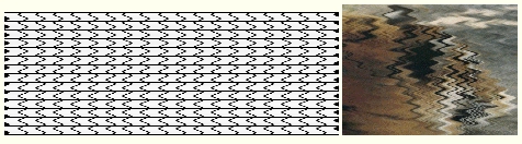
Calm Sea: The Calm Sea preset will make the selected region appear as though small ripples have been applied to the image. This is done using all Front based X waves with an amplitude of 20. This preset will give the image a gentle rolling look, much like a calm body of water. The grid below shows the application of this preset to the entire image.
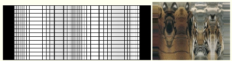
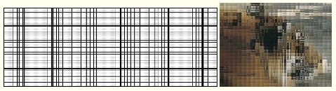
Stretch: Stretch creates a fun house mirror effect in the selected area. This is done by stretching the center of the image horizontally. The Waves dialog is set to have only two frontal waves of a small amplitude. You can increase the amplitude to increase the effect. The grid below shows the application of this preset to the entire image.
| Quick Nav Bar | ||||||||
|---|---|---|---|---|---|---|---|---|
| << Previous | Contents |
Selection |
Op Index |
Parent | User Notes |
Index |
Glossary |
Next >> |
| WinImages F/x Manual Version 7, Revision 5, Level B |